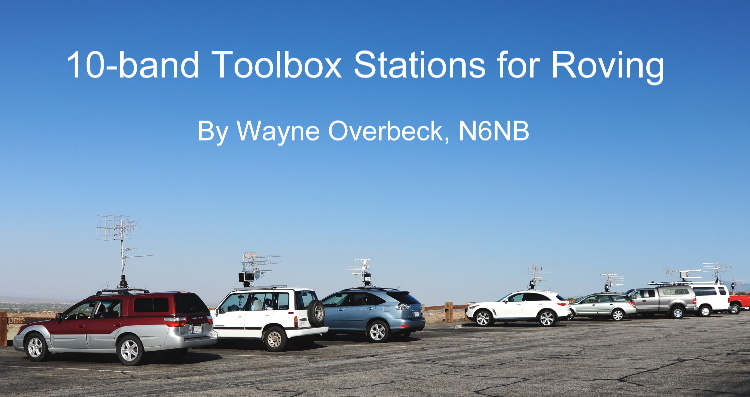
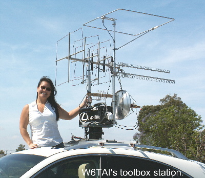
 Eight rovers pause for a photo opportunity near Palmdale, Calif. during
the August, 2009 UHF contest. Five are using 10-band "toolbox" stations
mounted on roof racks or, in one case, a truck bed.
Eight rovers pause for a photo opportunity near Palmdale, Calif. during
the August, 2009 UHF contest. Five are using 10-band "toolbox" stations
mounted on roof racks or, in one case, a truck bed.
This is based on a paper that was prepared for the
Proceedings of the 2009 Microwave Update in Irving, TX.
Ever since N6NBs 10-band toolbox rover
stations began to attract attention on the Internet, there has been a stream
of e-mail inquiring about them with questions like, what are they? and
whats inside those boxes?
The short answer is that these stations cover
10 VHF+ bands in a compact, portable package. Each station has six
UHF/microwave transverters and in some cases small amplifiers, all in a
20 Craftsman steel toolbox from Sears. Each toolbox has two short
masts, one on each side, to support antennas for as many as 10 VHF+ bands.
The toolboxes also have cooling fans and remotely controlled switching.
The toolboxes sit atop an antenna rotor on a roof platform that can be
adapted to almost any roof rack on a truck or SUV. Each toolbox station
also includes a console that normally rides on the passenger seat of a
car. The console has at least two transceivers (sometimes three)
to cover 50, 144, 222 and 432 MHz, plus a rotator control and an inverter
to power the rotor, a Rubidium frequency standard, and a remote control
head for the equipment in the toolbox. Fig. 1 and 2 at the end of
this article are block diagrams of a typical operating console and toolbox.
These units can be powered by an auxiliary storage battery and charged
by a connection to a cigarette lighter outlet. Of course, better
performance is possible with a high-current connection to a car battery.
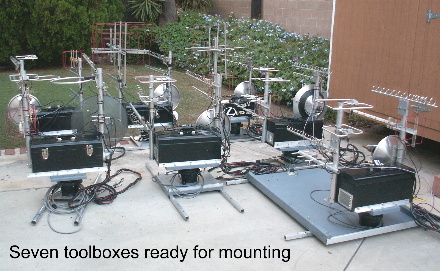
 I have built seven of these 10-band toolbox stations as well as four larger
10-band stations that can be used in vehicles with more space such as a
truck or a van. One of these larger stations is equipped with vacuum
tube kilowatt amplifiers for six and two meters, powered by a 3000-watt
inverter and a bank of batteries charged by a heavy duty alternator.
That station also has solid state amplifiers for all higher bands through
10 GHZ. But even toolbox stations built around transverters that
deliver less than one watt of power output are effective over long microwave
paths, thanks to their high gain antennas and short feedlines. With
their portability and simple installation requirements, these stations
make it easy to promote activity on the microwave amateur bands even in
areas that have no tradition of activity on those bands.
I have built seven of these 10-band toolbox stations as well as four larger
10-band stations that can be used in vehicles with more space such as a
truck or a van. One of these larger stations is equipped with vacuum
tube kilowatt amplifiers for six and two meters, powered by a 3000-watt
inverter and a bank of batteries charged by a heavy duty alternator.
That station also has solid state amplifiers for all higher bands through
10 GHZ. But even toolbox stations built around transverters that
deliver less than one watt of power output are effective over long microwave
paths, thanks to their high gain antennas and short feedlines. With
their portability and simple installation requirements, these stations
make it easy to promote activity on the microwave amateur bands even in
areas that have no tradition of activity on those bands.
THE TOOLBOX ITSELF - Each toolbox station has a combination of
Downeast Microwave (DEM) and Kuhne (DB6NT) transverters for 902, 1296,
2.3 GHz, 3.4 GHZ, 5.7 GHz and 10 GHz. All use DEM transverters on
902 and most use DB6NT transverters on 1296. The rest of the transverters
may be either brand, depending on a number of circumstances. With
either brand, its possible to fit six transverters plus one or two small
amplifiers into the toolbox.
Each toolbox has at least one cooling fan;
some have two. Warm air is vented out through a water-resistant port
that also provides access for control, power and antenna cables.
There is insulating material in the lid of the toolboxes to reduce equipment
heating. Experience has shown that these toolbox stations are reliable
even at summertime temperatures of 110 degrees Fahrenheit in the California
desert. The first toolboxes had insulation but no cooling fans--and
it quickly became apparent that more cooling was needed.
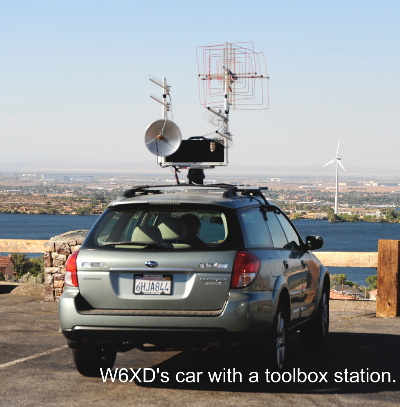
 The two masts support antennas for up to 10 bands in a compact, easily
transported package. All of the toolboxes have small (usually 30
cm.) dish antennas for 5.7 and 10 GHz, using W5LUA-type dual band feed
horns. The toolboxes use short loop Yagis on 2.3 and 3.4 GHZ.
Some also have loop Yagis on 902 and 1296. Others have quad or Quagi
antennas for those bands. Some have a triband 3-element quad antenna
for 144, 222, and 432 MHz as well. Others have omnidirectional loop
antennas 144, 222 and 432. The most common antenna for six meters
is also a full-wave omni loop, although two of the larger stations use
two-element Moxons for six meters.
The two masts support antennas for up to 10 bands in a compact, easily
transported package. All of the toolboxes have small (usually 30
cm.) dish antennas for 5.7 and 10 GHz, using W5LUA-type dual band feed
horns. The toolboxes use short loop Yagis on 2.3 and 3.4 GHZ.
Some also have loop Yagis on 902 and 1296. Others have quad or Quagi
antennas for those bands. Some have a triband 3-element quad antenna
for 144, 222, and 432 MHz as well. Others have omnidirectional loop
antennas 144, 222 and 432. The most common antenna for six meters
is also a full-wave omni loop, although two of the larger stations use
two-element Moxons for six meters.
One significant advantage of the toolbox design
is that the feedlines can be kept very short, minimizing losses.
Even at 10 GHz, feedline losses are typically below 1 dB. Because
the entire package--including equipment and antennas--rotates together,
semi-rigid cables can be used on the microwave bands. Only a bundle
of more forgiving cables (power and control cables plus RG-58 type
feedlines for lower frequencies) needs to be free to rotate. Even
those cables are usually less than 15 feet long.
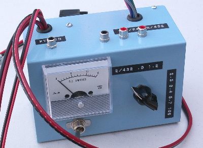
CONTROL ARRANGEMENTS Instant, single-knob bandswitching is
crucial for these rover stations, even on the microwave bands. That
is accomplished with a remote control head at the operating console and
a relay box inside each toolbox.
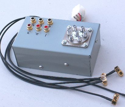 Each control head is similar to the one shown in the photographs.
All use the same cabling arrangements for interoperability. Each
has a DC ammeter to allow the current drawn by the toolbox to be continuously
monitored. Since the individual transverters and amplifiers are not
visible, the ammeter is used to keep track of what is going on in the toolbox.
If theres no increase in current when a transverter is keyed, that would
most likely indicate a failure in the keying circuitry for that band.
No current drain when the main power switch on the control head is turned
on would probably indicate a failure of the DC power connections to the
toolbox or perhaps a blown fuse.
Each control head is similar to the one shown in the photographs.
All use the same cabling arrangements for interoperability. Each
has a DC ammeter to allow the current drawn by the toolbox to be continuously
monitored. Since the individual transverters and amplifiers are not
visible, the ammeter is used to keep track of what is going on in the toolbox.
If theres no increase in current when a transverter is keyed, that would
most likely indicate a failure in the keying circuitry for that band.
No current drain when the main power switch on the control head is turned
on would probably indicate a failure of the DC power connections to the
toolbox or perhaps a blown fuse.
Bandswitching is accomplished with a multi-position
rotary switch on the control head. In the through or 2/432 position,
a relay at the i.f. transceiver engages to allow straight through operation
on the VHF bands. All keying circuitry in the toolbox is disabled
in this position. When the operator switches to any band from 902
on up, 24 volts is sent to the appropriate contacts on a six-position SMA
relay in the switching box in the toolbox. The 24 volts also
engages a double pole relay for that particular band, transferring the
PTT line and the 10 MHz Rubidium reference signal to the proper transverter.
The Rubidium unit and its 24-volt power supply are housed in the operating
console and connected to the toolbox with a single coaxial cable.
 OPERATING
CONSOLE Each operating console is similar to the one shown in the
photograph, although a variety of hardware is used in various stations.
Each station has a 222 MHz transceiver for intercommunications. Some
use a mobile FM transceiver, while others have a transverter and a separate
28 MHz transceiver for always-on 222 monitoring as well as SSB/CW capability.
Some stations also have a brick amplifier on 222. Having constant
liaison is essential for moving quickly through the higher bands. OPERATING
CONSOLE Each operating console is similar to the one shown in the
photograph, although a variety of hardware is used in various stations.
Each station has a 222 MHz transceiver for intercommunications. Some
use a mobile FM transceiver, while others have a transverter and a separate
28 MHz transceiver for always-on 222 monitoring as well as SSB/CW capability.
Some stations also have a brick amplifier on 222. Having constant
liaison is essential for moving quickly through the higher bands.
Many of the stations use a single 100-watt
HF/50 MHz transceiver that also covers 144 and 432. The transceiver
runs straight through for the bands through 432. In several of the
most compact stations, the same transceiver is the i.f. rig for the
transverters on 902 and higher bands. Some more elaborate stations
have a separate transceiver and amplifiers for 6, 2 and 432 and are capable
of at least 100 watts output on two meters and 75 watts on 432. Some
have more potent amps for even higher power on the VHF bands.
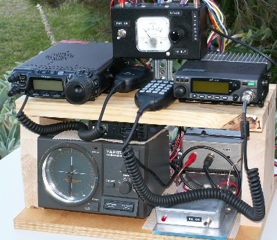 The Rubidium unit and its power supply are always located in the operating
console. Every console also has a control unit for an antenna rotator
as well as a power inverter to provide 110 volts for the rotor. Although
the console is usually strapped to the passenger seat of a car for
single-person operation, it is more convenient to mount the console on
the rear seat if a station will have a driver as well as an operator.
Some have tried to operate a station in the passenger seat from the back
seat, with consistently bad results.
The Rubidium unit and its power supply are always located in the operating
console. Every console also has a control unit for an antenna rotator
as well as a power inverter to provide 110 volts for the rotor. Although
the console is usually strapped to the passenger seat of a car for
single-person operation, it is more convenient to mount the console on
the rear seat if a station will have a driver as well as an operator.
Some have tried to operate a station in the passenger seat from the back
seat, with consistently bad results.
Many operators have their own favorite GPS
unit that they carry with them. Some also have a digital voice recorder
for logging on the fly while driving. Some try logging on a personal
computer while driving. The wiser ones soon decide that isnt a particularly
good idea. Of course, some also have a c.w. paddle that they use
for mobile weak-signal operating.
ROTORS, PLATFORMS AND DC POWER It has to be possible to mount
and dismount the toolbox stations quickly. With 11 stations to install
during the week before a VHF contest, I was forced to come up with easy
ways to accomplish the task. A variety of platforms have been built
to allow a toolbox and antenna rotor to be attached to any vehicle that
has a roof rack or a truck rack. Sometimes toolbox stations have
been installed in the bed of a truck or inside the rear of an SUV, although
that arrangement makes rotating the antennas much more inconvenient if
not impossible. But not everyone who may use one of these stations
in a contest owns an SUV or truck with a rack.
Once a platform with a rotor is secured to
a roof rack or some other stable surface, the toolbox is lifted onto the
rotor and attached with four bolts. Experience has shown that this
arrangement is quite stable. No rotor has ever failed because of
the weight or windload of a toolbox station. Yaesu rotors are used
for all of these installations because the toolbox can be bolted directly
atop the rotor without any mast or pipe bracket. Mounting the toolbox
directly on the rotor body reduces stresses on the rotor, perhaps accounting
for the reliability of these installations.
 Providing DC power to the toolbox stations is a more difficult challenge
in some cases. Ideally, a heavy primary cable (at least #10) runs
directly from the operating console to the car battery. Operators
are always advised to leave the engine running while on the air for an
extended period of time.
Providing DC power to the toolbox stations is a more difficult challenge
in some cases. Ideally, a heavy primary cable (at least #10) runs
directly from the operating console to the car battery. Operators
are always advised to leave the engine running while on the air for an
extended period of time.
If a station has to be installed in a vehicle
that lacks a heavy cable to the battery, the second-best alternative is
an auxiliary battery near the console, recharged by a cigarette lighter
plug. This is not an ideal arrangement because few lighter circuits
are intended for this kind of current demand. Dead auxiliary batteries
are a common occurrence when an ambitious operator does a lot of transmitting
at the 100-watt (or higher) level, even with the engine running and a recharging
circuit properly plugged in.
STATION PERFORMANCE - The inevitable question about these stations
is always, how well do they work? The answer, of course, is it
depends. Under good conditions, any of the 11 stations discussed
here is capable of working 1000 km. into Mexico on 10 GHz. Several
of them have been in the right place at the right time to do just that.
Under mediocre conditions with typical mobile noise on a freeway, all are
capable of working well-equipped stations several hundred kilometers away
if the terrain is clear. What these stations offer is a way to get
on 10 VHF+ bands quickly with well-tested setups that are ready to go on
short notice. Considering how much trouble most of us had getting
our first 10-band VHF+ station running, these stations have proven to be
remarkably trouble free. Its not unusual to get through an entire
contest with every station still working on every band when its over.
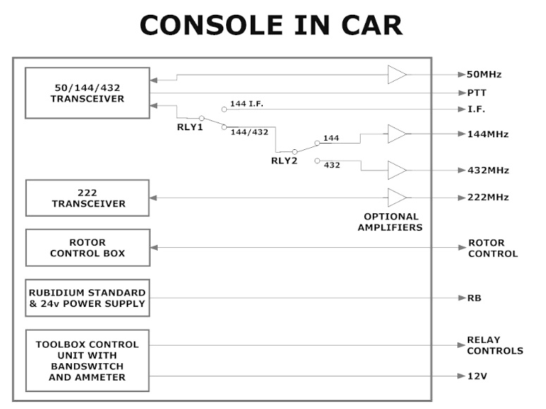
Fig. 1. A typical operating console that mounts inside a car to
control a toolbox station.
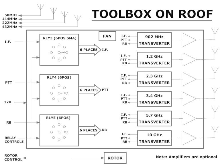
Fig. 2. A typical toolbox assembly for auto rooftop mounting.
Thanks to Jim Forsyth, AF6O, for drafting these figures.
__________________
About the author: First licensed in 1957, Wayne Overbeck has
been interested in VHF+ operating, and especially portable contesting,
for more than 50 years. He holds Ph.D. and J.D. degrees and is a
retired Professor of Communications at California State University, Fullerton.
He is the senior author of a communications law textbook that is now in
its 21st edition. He won the Radio Amateur of the Year Award at the
Dayton Hamvention in 1980 as well as the ARRL Technical Excellence Award
and the John Chambers Memorial Award of the Central States VHF Society
in 1978. The latter awards were in recognition of his work on the
original VHF Quagi antenna and his early moonbounce expeditions to Alaska
and the Utah-Nevada border. See www.n6nb.com for more information
about many of these subjects.
<return to N6NB page>
|