The Quagi Antenna Turns 50
By Wayne Overbeck, N6NB
www.n6nb.com
It has been 50 years since the VHF-UHF Quagi antenna--a
combination of the desirable features of a Yagi and a cubical quad--was
developed and the design was first published in the newsletter of the Southern
California VHF Club, a forerunner of today's Western States Weak Signal
Society.
After the first prototype Quagi antennas were measured
for gain at the 1972 West Coast VHF Conference in Santa Clara, Calif.,
word began to spread about these simple and easy-to-duplicate but effective
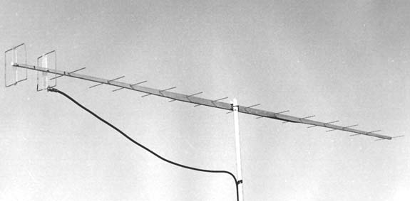
antennas. The original 8-element design was published in the April,
1977 issue of QST magazine. A follow-up article in QST
for February, 1978 described the 15-element 432 MHz version (shown above).
A third article, describing Quagi antennas for 1296 MHz, appeared in the
August, 1981 QST.
The antenna, which is usually built with little
more than hardware store materials, became popular in many parts of the
world. The original design was republished in amateur radio publications
in countries as diverse as the former Soviet Union and India. Thousands
of them have been built over the years.
Some Quagi history
The Quagi was originally designed on the K6YNB/N6NB
backyard antenna range in 1972, with the assistance of Will Anderson, WB6RIV/AA6DD
(check out the 1972 photo of Will at the end of this article). Later
work on the larger Quagi designs was done in a city park and on a beach
in an attempt to get away from reflections and obstructions that made the
task of optimizing the antenna design in a small backyard more difficult.
What originally inspired the development of
the Quagi antenna was the need for a low-cost, high-gain antenna for moonbounce
communications. Some of the commercial antennas then available fell
far short of their advertised gain figures, especially at 432 MHz.
After a series of attempts to improve the performance of one particular
commercial 11-element Yagi, attention was focused on the driven element--which
had an especially inefficient gamma match. On a hunch, the
driven element was removed and replaced with a quad-style loop. The
forward gain immediately increased from 6.4 dBd. to 9.8 dBd--a dramatic
improvement for an antenna rated by the manufacturer at 13 dBd.
That led to exhaustive efforts to optimize
this hybrid antenna, working originally at 222 MHz. After many experiments,
it was determined that Yagi-style directors delivered better gain than
quad loops when the antenna was extended beyond four or five elements.
But the use of a quad-style driven element and reflector offered several
advantages, including good gain, good immunity to noise resulting from
static buildup, and extreme ease of construction and impedance matching.
After many designs were tried and rejected, the classic 8-element and 15-element
designs were selected for publication. Later additional designs for
1296 were developed.
Antenna range methodology
In this era of computer-optimized antenna
designs, many radio amateurs are amazed that anyone would actually set
up a home antenna range and perform the tedious job of designing an antenna
one element at a time.
Computer modeling has revolutionized the way radio
amateurs look at antennas. Armed with one of the powerful software
packages that have come along in recent years, it is possible to design
more antennas in a day than could be designed in a lifetime on an antenna
range. Consequently, actual field measurement of antennas--using
the classic scientific method of experimental research--has gone out of
fashion.
However, computer modeling has its limitations.
It is not always possible to model all of the variables that come into
play with real-world antennas. And the modeling process has pitfalls
even for the experts. Well-known software producer Brian Beezley,
K6STI, published an article in Vol. 4 of the ARRL Antenna Compendium
called
"An Adventure in Antenna Modeling," in which he described his own frustrating
attempt to design an antenna with exceptional low-angle radiation.
Concluding, he said this: "In the end I decided to write up this
fiasco for several reasons. First, I wanted to demonstrate how foolish
it's possible to become when you get carried away with computer modeling.
Powerful software is no substitute for common sense. Second, I wanted
to point out how easy it is to draw invalid conclusions when you ignore
the limitations of antenna-modeling algorithms."
Roy Lewallen, W7EL, another well-known modeling
software author, said much the same thing in a February, 1991, QST
article, "MININEC: The Other Edge of the Sword." He cited an
example of an amateur whose computer modeling showed that a dipole less
than a foot above a poor ground yielded 45 decibels gain over a dipole.
Of that amateur, Lewallen said, "...he recognized that the answer was ridiculous,
but sometimes we're not so lucky and the errors are tougher to spot."
Well then, how can a radio amateur who wants first-rate
antenna performance be certain an antenna is really working as it should--or
design a brand-new antenna?
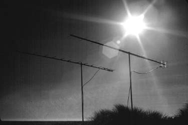 One answer is to measure the antenna's gain against a known reference.
Antenna gain measuring sessions have been conducted at VHF/UHF conferences
since the 1950s. Often these sessions, in which antennas are sometimes
measured side by side as shown in the 1977 photo at left, are conducted
by antenna experts using professional quality signal sources and measuring
instruments. But any amateur willing to invest some time can set
up an antenna range somewhere and obtain accurate antenna gain measurements
with nothing more sophisticated than a low-power transmitter, a receiver
and an audio VU meter. I published an article in
QST
in October, 1977, called "Measuring Antenna Gain with Amateur Methods"
to describe the procedures for doing this.
One answer is to measure the antenna's gain against a known reference.
Antenna gain measuring sessions have been conducted at VHF/UHF conferences
since the 1950s. Often these sessions, in which antennas are sometimes
measured side by side as shown in the 1977 photo at left, are conducted
by antenna experts using professional quality signal sources and measuring
instruments. But any amateur willing to invest some time can set
up an antenna range somewhere and obtain accurate antenna gain measurements
with nothing more sophisticated than a low-power transmitter, a receiver
and an audio VU meter. I published an article in
QST
in October, 1977, called "Measuring Antenna Gain with Amateur Methods"
to describe the procedures for doing this.
Because so few amateurs do actual gain measurements
today, it seems worthwhile to summarize what that article said here.
The article said that any clear area can be an antenna
range. The trick is to avoid obstructions and reflections:
if the received signal is louder when the antenna is pointed away from
the source, there is a problem.
To conduct comparison tests, two antennas are placed
side by side on masts of the same height, using equal length feedlines.
A steady signal (a carrier) is generated perhaps 40 wavelengths away, and
it is detected on a CW/SSB receiver that is not overloaded but has
its AGC disabled. Then a VU meter can be used to indicate the difference
in received signal strength of the two antennas. As a precaution,
the two antennas are swapped so that antenna #1 goes on the mast and uses
the feedline formerly used by antenna #2. Given some care in measurements
and a stable path, it is possible to determine the difference in the gain
of the two antennas down to a fraction of a decibel.
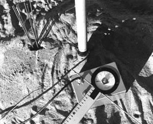
Once the experimenter has confidence in the
integrity of the antenna range, it's quite possible to dispense with the
receiver and VU meter and use a signal source plus a field strength meter
such as the one shown in the photo at right (which also shows an assortment
of elements of varying lengths, including one mounted on a meter stick
for use in antenna design work).
Incidentally, although this test setup is most practical
with VHF/UHF antennas, the same principles work at HF as well if one can
obtain the right hardware (e.g., a tower trailer to support a reference
antenna beside each antenna being tested). Also, new antennas can
be designed using these antenna range principles. A variety of element
length and spacing combinations can be tried until the best results are
achieved. While this is far more tedious than computer modeling,
it does produce repeatable, practical real-world results. The Quagi
antenna was designed in this fashion in 1972.
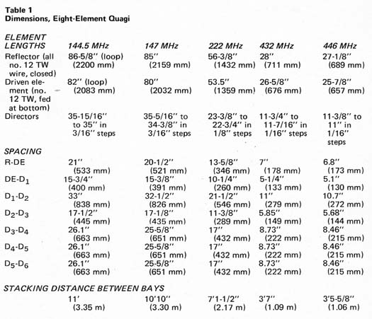
 In the original Quagi development at 222 MHz, Will and I first started
working with cubical quad-style loop elements until we were satisfied that
we had loops that were performing as they should. Then we added elements,
first using loops and then rod directors. We tried various lengths
for each new element and adjusted the spacing for maximum gain. The
addition of each new element, of course, required us to re-check the previous
elements for length and spacing, monitoring the gain of the antenna during
each change. After a lot of painstaking experimentation, we arrived
at the designs for 144, 222 and 432 MHz that were eventually published.
The 1296 antennas were designed five years later at N6NB's antenna farm
in Woodland Hills, which was the forerunner of the Tehachapi Mountain antenna
farm.
In the original Quagi development at 222 MHz, Will and I first started
working with cubical quad-style loop elements until we were satisfied that
we had loops that were performing as they should. Then we added elements,
first using loops and then rod directors. We tried various lengths
for each new element and adjusted the spacing for maximum gain. The
addition of each new element, of course, required us to re-check the previous
elements for length and spacing, monitoring the gain of the antenna during
each change. After a lot of painstaking experimentation, we arrived
at the designs for 144, 222 and 432 MHz that were eventually published.
The 1296 antennas were designed five years later at N6NB's antenna farm
in Woodland Hills, which was the forerunner of the Tehachapi Mountain antenna
farm.
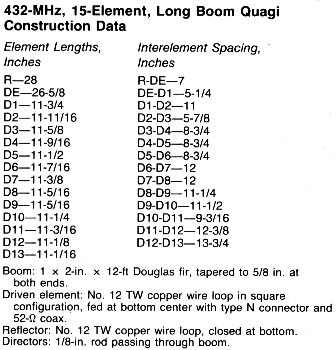
Quagi construction notes for 144, 222 and 432 MHz
The original Quagi antennas used wooden booms
(1x2 or 1x3 Douglas Fir, tapered at both ends to reduce the weight and
wind load), but any other nonconductor (e.g., fiberglass, Plexiglas or
even taped bamboo) can also be used. If an aluminum boom is used,
the elements should be mounted on insulators above or below the boom (not
passed through a metal boom). Many builders have used small pieces
of hardwood moulding to mount the directors atop an aluminum boom.
 The driven element and reflector are mounted on
nonconductive spreaders such as dowel rods or strips of Plexiglas to avoid
interaction. The driven element has a coaxial connector (an SO-239
or type-N connector, which is preferable at UHF) at the center of the bottom
side of the element and is fed directly with 50-Ohm coaxial cable.
In the original design, covered solid #12 TW house wire was used for the
quad-style elements. The use of other types of wire, or even removing
the insulation, may change the resonant frequency enough that the length
has to be adjusted. Suggestion: build the antenna to the dimensions
shown in the chart and run an SWR curve, noting the SWR above and below
the desired operating frequency. If it is lowest below the desired
frequency, the driven element should be made shorter--or longer if the
SWR is lowest above the desired frequency. The reflector should then
be adjusted in length a similar amount. Many builders have used
THHN wire, which is more readily available than type TW now. They
generally report that the resonant frequency is higher than expected, which
means the loop elements have to be lengthened slightly for THHN wire.
Tests in 2003 indicated that each wire loop should be about one percent
longer than the original dimension if THHN wire is used.
The driven element and reflector are mounted on
nonconductive spreaders such as dowel rods or strips of Plexiglas to avoid
interaction. The driven element has a coaxial connector (an SO-239
or type-N connector, which is preferable at UHF) at the center of the bottom
side of the element and is fed directly with 50-Ohm coaxial cable.
In the original design, covered solid #12 TW house wire was used for the
quad-style elements. The use of other types of wire, or even removing
the insulation, may change the resonant frequency enough that the length
has to be adjusted. Suggestion: build the antenna to the dimensions
shown in the chart and run an SWR curve, noting the SWR above and below
the desired operating frequency. If it is lowest below the desired
frequency, the driven element should be made shorter--or longer if the
SWR is lowest above the desired frequency. The reflector should then
be adjusted in length a similar amount. Many builders have used
THHN wire, which is more readily available than type TW now. They
generally report that the resonant frequency is higher than expected, which
means the loop elements have to be lengthened slightly for THHN wire.
Tests in 2003 indicated that each wire loop should be about one percent
longer than the original dimension if THHN wire is used.
Fine-tuning of the element length is usually
not needed for the directors, provided they are made of 1/8-inch aluminum
rods, brass welding rods or something similar--as long as the boom is a
nonconductor or the elements are mounted on insulators above or below the
boom. If the elements pass through a metal boom (even with insulating
sleeves), the length will have to be adjusted experimentally (have fun!).
The director lengths are tapered from longest (closest to the driven element)
to shortest (at the front of the antenna).
Although the quad loops are square or circular,
the antenna is linear in polarization, not circular. If it is fed
at the bottom, the antenna will be horizontally polarized. Feed the
antenna on either side for vertical polarization (and then mount the directors
vertically, not horizontally.
Some builders have tried baluns to correct
the imbalance in this quad-style feed arrangement. In many cases,
a balun introduces losses so great that it's better to live with the unbalanced
feed than to try to correct it. Feedline radiation can be reduced
by placing toroids on the feedline at the antenna. Also, the feedline
should run away from the feedpoint along the boom or below it--and then
down the supporting mast perpendicularly to the elements to avoid interaction
problems.
A phasing harness is needed if two or more
Quagi antennas are stacked for additional gain. The simplest way
to feed multiple bays is with a commercial power divider and equal-length
50-ohm feedlines from the power divider to each antenna. An alternative
method is to feed each pair of antennas with odd quarter-wavelength multiples
of 75-ohm coaxial cable going to a T connector and with 50-ohm cable from
that point to the station. Most amateur radio reference books describe
phasing harnesses more fully.
 With a little practice, these antennas can be mass-produced in large quantities
at low cost. I have built as many as 16 of them for e.m.e. work in
less than a day.
With a little practice, these antennas can be mass-produced in large quantities
at low cost. I have built as many as 16 of them for e.m.e. work in
less than a day.
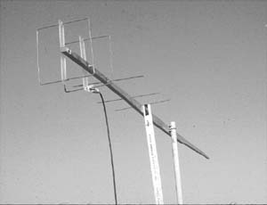
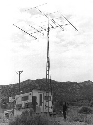
Performance? Quagi antennas have been
measured for gain at VHF conferences many times. If well built, the
8-element model usually comes in between 12 and 13 dBd. forward gain over
a dipole, while the 15-element model is around 14-15 dBd. gain. These
antennas have been used by a number of record-setting VHF-UHF contest stations,
sometimes in portable applications like the one shown in the photo here.
This photo, taken in 1976 at Utah Pass, Utah
shows an installation of six Quagi antennas (two each for 144, 222 and
432 MHz) plus a Yagi for 50 MHz. They are mounted on the original
"Cabover Kilowatt" contest truck, which was featured on the cover of QST
in August, 1971.
Original Quagi dimensions
(from April, 1977 QST)
Dimensions of 1296 MHz Quagi antennas
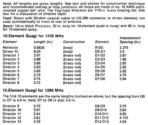
Notes concerning the 1296 MHz antenna design
At 1296 MHz, even small variations in the dimensions
can have a dramatic effect on the antenna's performance. In the original
design, the reflector loop was overlapped by 1/8 inch and soldered together
after being fitted through holes drilled in a plexiglas "spreader" mounted
on the boom. The driven element loop was soldered to a standard UG-290
chassis-mount BNC connector. One end of the 9.25-inch loop was pushed
as far as it would go into the center pin and soldered. Then the
loop was shaped and threaded through a plexiglas spreader. Finally,
the other end was fed into one of the four mounting holes on the BNC connector
and soldered. In most cases, the best VSWR was obtained if the end of the
wire just passed through the hole so that it was flush with the opposite
side of the connector. These lengths can be optimized if a reflected
power meter that works at 1296 MHz is available: the length of the
driven element can be adjusted slightly for lowest reflected power.
If a major change has to be made, the reflector should be adjusted a comparable
amount. The loop elements were shaped into a square; the exact shape
did not appear to be critical.
The directors were made as follows.
Using 1/16-inch brass welding rod, one director was cut just slightly shorter
than four inches and then filed down as needed. Then another was
cut and filed to the shortest dimension, as well as that could be determined
with a good ruler. Finally, all of the intermediate elements were
filed so that they tapered evenly in length from the longest (3.91 inches)
to the shortest (3.59 inches in the case of the 15-element model).
This information concerning the 1296 Quagi
first appeared in the August, 1981, issue of QST.
 Here
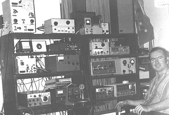
is Will Anderson, then WB6RIV, with a modern HF-VHF-UHF station, circa
1972. How much of this equipment can you identify? Here
is Will Anderson, then WB6RIV, with a modern HF-VHF-UHF station, circa
1972. How much of this equipment can you identify?
Some of the obviously homebrewed equipment
includes (top left to right) an HF kilowatt amplifier, a two-meter 4CX250B
amplifier, and a high voltage power supply. Directly below that there
is a 500-watt amplitude-modulated 222 MHz rig that Will used for years
as net control of the "220 Rag and Tech Net" on Sunday nights. Not
shown is a 50 MHz amplifer that used a pair of 3-500z tubes (almost identical
in appearance to the HF kilowatt). Below the HF kilowatt and two
antenna rotor controls is a stripline 144 MHz kilowatt using push-pull
4CX250B tubes. To its right is a 28-to-50-MHz transverter using parallel
6146s in the final. The Heathkit SB-200 amplifier to the right of
the transverter had been converted for six meters. To its right is
the plate modulator for the 222 MHz rig. On the bottom shelf there
is a Drake TR-3 HF transceiver, a Swan TV-2 transverter for two meters,
a Drake TR-6 for six meters and a Hallicrafters HF receiver. A surprising
amount of this equipment still works 40-50 years after it was built!
<return to N6NB page>
|