Measuring antenna gain
Practical
ways to get accurate results
Computer modeling has revolutionized the way radio
amateurs look at antennas. Armed with one of the powerful software
packages that have come along in recent years, it is possible to design
more antennas in a day than could be designed in a lifetime on an antenna
range. Consequently, actual field measurement of antennas--using
the classic scientific method of experimental research--has gone out of
fashion.
However, computer modeling has its limitations.
It is not always possible to model all of the variables that come into
play with real-world antennas. And the modeling process has pitfalls
even for the experts. Well-known software producer Brian Beezley,
K6STI, published an article in Vol. 4 of the ARRL Antenna Compendium
called
"An Adventure in Antenna Modeling," in which he described his own frustrating
attempt to design an antenna with exceptional low-angle radiation.
Concluding, he said this: "In the end I decided to write up this
fiasco for several reasons. First, I wanted to demonstrate how foolish
it's possible to become when you get carried away with computer modeling.
Powerful software is no substitute for common sense. Second, I wanted
to point out how easy it is to draw invalid conclusions when you ignore
the limitations of antenna-modeling algorithms."
Roy Lewallen, W7EL, another well-known modeling
software author, said much the same thing in a February, 1991, QST
article, "MININEC: The Other Edge of the Sword." He cited an
example of an amateur whose computer modeling showed that a dipole less
than a foot above a poor ground yielded 45 decibels gain over a dipole.
Of that amateur, Lewallen said, "...he recognized that the answer was ridiculous,
but sometimes we're not so lucky and the errors are tougher to spot."
Well then, how can a radio amateur who wants first-rate
antenna performance be certain an antenna is really working as it should?
One answer is to measure the antenna's gain against
a known reference. Antenna gain measuring sessions have been conducted
at VHF/UHF conferences since the 1960s. Often these sessions are
conducted by antenna experts using professional quality signal sources
and measuring instruments. But any amateur willing to invest some
time can set up an antenna range somewhere and obtain accurate antenna
gain measurements with nothing more sophisticated than a low-power transmitter,
a receiver and an audio VU meter. I published an article in
QST
in October, 1977, called "Measuring Antenna Gain with Amateur Methods"
to describe these methods.
Because so few amateurs do actual gain measurements
today, it seemed worthwhile to summarize what that article said on this
web page.
The article said that any clear area can be an antenna
range. The trick is to avoid obstructions and reflections:
if the received signal is louder when the antenna is pointed away from
the source, there is a problem.
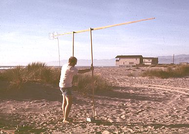
To conduct comparison tests, two antennas are placed
side by side on masts of the same height, using equal length feedlines.
A steady signal (a carrier) is generated perhaps 40 wavelengths away, and
it is detected on a CW/SSB receiver that is not overloaded but has
its AGC disabled. Then a VU meter can be used to indicate the difference
in received signal strength of the two antennas. As a precaution,
the two antennas are swapped so that antenna #1 goes on the mast and uses
the feedline formerly used by antenna #2. Given some care in measurements
and a stable path, it is possible to determine the difference in the gain
of the two antennas down to a fraction of a decibel.
Although this test setup is most practical with
VHF/UHF antennas, the same principles work at HF as well if one can obtain
the right hardware (e.g., a tower trailer to support a reference antenna
beside each antenna being tested). Also, new antennas can be designed
using these antenna range principles. A variety of element length
and spacing combinations can be tried until the best results are achieved.
While this is far more tedious than computer modeling, it does produce
repeatable, practical real-world results. The Quagi antenna was designed
in this fashion in 1972. The accompanying photographs illustrate
how an antenna range can be set up and used.
 A
seaside antenna range... A
seaside antenna range...
...designing a new antenna by substituting elements while
watching a meter.
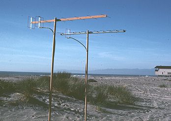
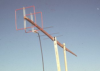 A
closeup view of the design process... A
closeup view of the design process...
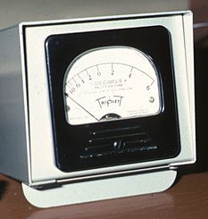
A simple meter gives a readout in dB.
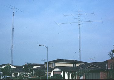
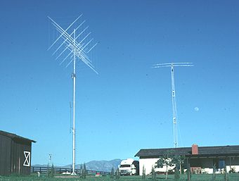 Measuring
the gain of a large HF quad... Measuring
the gain of a large HF quad...
Conducting a similar measurement of a large Yagi array...
A final note: after measuring dozens of HF
antennas against the reference antenna shown here, I published an article
in Ham Radio magazine called, "Quads and Yagis Revisited" (May,
1979). It concluded that the oft-claimed superiority of the quad
design was not observable in these field measurements--at low radiation
angles, high angles or anywhere in between.
-Wayne Overbeck, N6NB
<return to N6NB page>
|